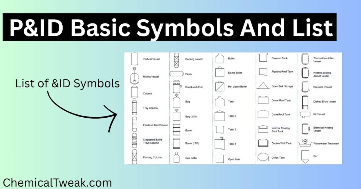
P&id diagram plays an important role in any type of industry to have an overview of process flow along with equipment and valves. To read p&id diagrams, it is important to know p&id diagram basics.
A P&ID diagram is a process and instrumentation diagram and are very useful for the chemical industries which will provide you Design and layout of the process system of a chemical plant. It is a detailed drawing that shows the piping, vessels, valves, pumps, and other process equipment.

A P&ID diagram plays an important role in any industry. It provides an overview of process flow, along with equipment and valves. To read P&ID diagrams, it is important to know the basics.
In this article, Chemical tweak will explain you the basic p&id diagrams which will help to understand the process and instrumentation diagram. Before we jump to the p&id diagram basics symbols, let us know first what is p&id diagram.
Table of Contents
What is p&id diagram?
P&ID diagram stands for Piping and instrument diagram also known as process and instrumentation diagram and it is also known as Process Engineering Flow Scheme (PEFS). A piping and instrumentation diagram (P&ID) is a detailed diagram in the process industry that shows the piping and vessels/equipment in the process flow, along with the instrumentation and control devices.
P&ID is a graphical representation of the plant consisting of piping, vessels, tanks, and equipment in detail. Before we get into the p&id diagram symbol.
What are the types of Process Flow Charts?
There are different types of process flow charts. The types of flow diagrams are described below
- Block diagram
- Process flow diagram
- Piping and instrumentation diagram (P&id diagram) / process and instrumentation diagram / Process Engineering Flow Scheme
Chemical tweak discussed types of process flow diagrams with examples in detail; you can learn from that.
All the different types of process diagrams serve different purposes and all are used accordingly. Likewise, in this article, let us check out the uses of piping and instrumentation diagrams and
P&ID diagram is very essential for a chemical engineer as it is the graphical representation of the whole chemical plant consisting of equipment, types of valve, types of pipelines identification, control valves and interlocks, and all the piping flow from the equipment i.e. vents, drain lines, special fittings tapping and sampling lines etc.
Now we know the definition of p&id diagrams so let us jump to what does p&id diagram includes
P&ID Diagram includes
- Process flow along with the Equipment used in the plant.
- Flow valves, types of flow valve,s and position of flow valves in plant (name and tags, identifier).
- Control valve type and location.
- Equipment is installed in the plant.
- Piping flow from the equipment to equipment, including vents, drain line, and special fitting tapping and sampling lines.
Note – Now all p&id diagrams include the above-listed points. The above-listed points are the optional sections that may or may not be included in the p&id diagrams.
Let us learn the uses of p&id diagram for which this p&id is prepared.
Uses of P&ID diagram
- Used to learn piping and equipment located in the plant.
- It is used to locate valves, pipes, and control valves.
- Used for maintenance & modification of the process.
- Used by mechanical technicians & safety personnel.
- Use to do optimization in plants.
Before we jump to the the article, let us read the note.
P&ID diagrams vary from organization to organization. You will find different types of P&ID diagrams used for the equipment in different companies.
P&ID diagram basics symbols/symbols used in P&ID diagrams
valve symbols p&id
P&ID diagram for Vessels and tanks

P&ID diagram for Pumps and compressor


P&ID diagram for heat exchanger
FAQ (p&id means)
1. What does p&id stand for?
P&id stands for piping and instrument diagram also known as process and instrumentation diagram
2. What is the meaning of P and ID?
In P&ID, P stands for piping and ID stands for instrument diagram.
3. What should be on a P&ID?
P&IDs show the piping, valves, and other process equipment, as well as the instrumentation and controls used to manage the process.
4. In which industries are P&ID used in?
P&ID is the essential document for any plant and it should be used in every industry such as chemical plants, petroleum, polymer, metallurgy, and in pharmaceuticals.
5. What is PEFS drawing?
PEFS stands for Process Engineering Flow Scheme (PEFS) which is also known as Piping and Instrumentation Diagram.
6. What are the Phases of P&ID?
There are different stages of P&ID and those are,
1. IFD – (Issued for Design)
2. IFR – (Issued for Review)
3. IFH – (Issued for HAZOP)
4. IFC – (Issued for Construction)
Wrapping Up
Hope you like the article on P&ID diagram basics and P&ID symbols and this article helped you to learn symbols used in P&ID diagrams and this article will help you to have a better understanding. These can be change from company to company, hence you should refer to the legend carefully. If you have any suggestions, then feel free to use the comment section.


Dear Ronak,
Please, send me some template by P&ID with nodes selected already and colored.
Many thanks in advance for your cooperation
you can search it on google. You will find plenty of them.
If you still struggle then do let me know.