Chemical engineering Process flow diagrams are extremely useful to understand any chemical manufacturing process. There are total 3 types of process flow diagram in chemical engineering and in this tutorial, we are going to learn what is pfd diagram and what are the types of with examples.

Before we get into the tutorial on what are the types of process flow diagram, lets have a quick introduction to what are process flow diagram.
What is a chemical engineering process flow diagram?
A process flow diagram (PFD) is a graphical representation of a chemical process. The PFD displays the relationship between the different process units in a clear, concise manner. It is commonly used in chemical engineering and process engineering.
Chemical Engineering Process flow diagrams help us understand the chemical process. These diagrams are fundamental and provide the overall details of the process in any chemical industry.
The PFD shows the general arrangement of the process units in a plant. It does not show detailed information such as pipe sizes, equipment types, or operating conditions. The PFD should include all major unit operations and supporting systems, such as utilities.
Types of process flow diagram?
To understand the process in the chemical industry or any other industry, there are different types of process flow diagram. Each type of process flow diagram provides specific details of the plant, described below.
- Block Flow Diagram (BFD)
- Process Flow Diagram (PFD)
- Piping & Instrumentation Diagram (P&ID)
1. Block Flow Diagram (BFD)
The Block Flow Diagram is the simplest form of a Flow Diagram for a chemical engineering process and typically shows the major pieces of equipment and the process steps. It is a good way to get an overview of the process, but it does not show all the details.
A Block flow diagram usually resembles a general material flow composed of rectangle boxes that includes the major equipment of the process industry. This type of diagram includes the chemical process flow along with equipment to provide an overview of the chemical plant and process.
Example of block flow diagram
Example 1:,
A block flow diagram for a simple distillation process might look like this:
The feed (liquid to be distilled) is heated in the boiler to create vapor. The vapor rises into the distillation column, where it comes into contact with the cooling water utility from the condenser. This causes the vapor to condense, and the condensed liquid flows into the reflux pot from that the condensed liquid is then collected in a collecting vessel.
Example 2:
The below diagram is an example of a block flow diagram. As you can see the whole manufacturing process is described as a block diagram. The process flow is described in a block flow diagram consisting of chemical process equipment in rectangular and square and process flow is described as arrow. In block diagram. The Block diagram does not include pipes, valve, interlock, etc, only the flow of the process through equipment are described.

2. Process Flow Diagram (PFD)
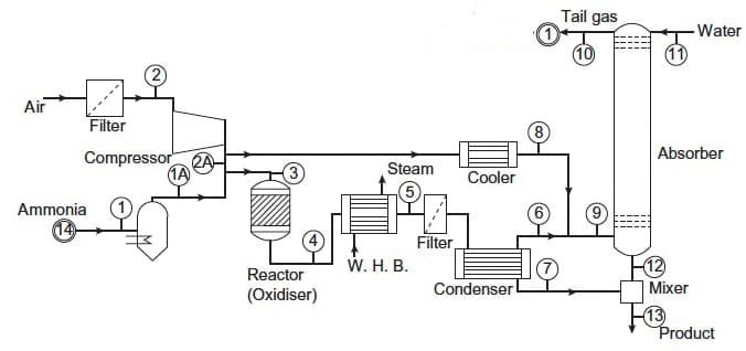
The Process Flow Diagram goes a little deep than the Block Flow Diagram in that it provides more detail about major equipment, subsystems, and process flow path. The Process flow diagram may or may not includes the process parameters like pressure and temperature information as well as the main parameters of the chemical plant and process.
Now let us understand the process flow diagram with examples. You can see the below figure of a process flow diagram. Process flow diagrams resemble the chemical process through symbols and processes in detail compare to block flow diagrams. The process flow diagram contains a specific diagram of the equipment containing information in deep.
Process flow diagrams Examples
3. Piping & Instrumentation Diagram (P&ID)
Piping and instrumentation diagram is also known as process and instrumentation diagram. This P&ID diagram is the detailed process flow diagram that includes more details about the process industry like pipes diameter including pipes types and identifications, valve types, control valve and interlocks and all the pipes flow i.e. vents, drain line special fittings tapping and sampling lines etc.
Example of P&ID diagram – Process and instrumentation diagram
We had discussed what are the types of p&id symbols in details where all the basic chemical engineering symbols are described.
FAQ (Process Flow Diagram (PFD))
1. What are the Types of flow diagrams in chemical engineering
There are 3 types of process flowcharts such as Block Flow Diagram (BFD), Process Flow Diagram (PFD) and Piping & Instrumentation Diagram (P&ID)
2. What are manufacturing process flow diagrams
Process flow diagrams provide you an overview of the manufacturing process which includes equipment and process flow.
3. What is the difference between P&ID and PFD?
A P&ID shows all of the piping, valves, and other equipment that is used in a process. It also shows the different inputs and outputs for each piece of equipment. A PFD, on the other hand, only shows the major pieces of equipment and doesn’t show all of the piping.
Another difference between P&IDs and PFDs is that P&IDs can be much more detailed than PFDs.
Wrapping Up
Hope this article on Types of Process flow diagram will help you to have a general idea on what is process flow diagram along with diagrams. Keep in touch with Chemical Tweak for more such chemical engineering topics. In the upcoming chemical tweak post, we will explore more such chemical engineering concepts in depth. If you have any suggestions, feel free to use the comment section. Your comment will be appreciated.


Good explanation.
Stephen VILAWA
The Chemical Engineering Process diagrams are explained with simple terms. I love it. Thank you very much.
Thanks